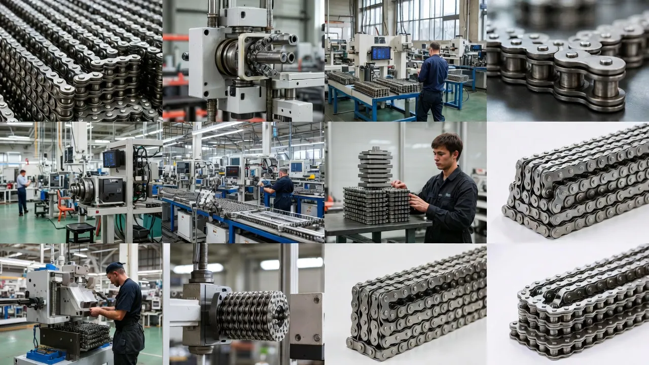
Engineering-grade single-strand roller chains built to withstand extreme loads, harsh environments, and continuous duty cycles across Australia’s most demanding industrial sectors.
Technical Specifications of Heavy Duty Simplex Chains
Selecting the right simplex roller chain starts with a clear understanding of dimensional tolerances, tensile ratings, and material designations. The table below consolidates the principal engineering parameters across the most common pitches deployed in heavy-duty Australian industrial installations, conforming to AS/ISO 606 and ANSI B29.1 standards.
Allowable loads are calculated at approximately 1/5 of minimum tensile strength — consistent with a safety factor of 5 recommended for industrial drives under shock-load conditions. Stainless steel variants carry slightly lower tensile ratings but offer superior corrosion resistance for food-grade or coastal environments.
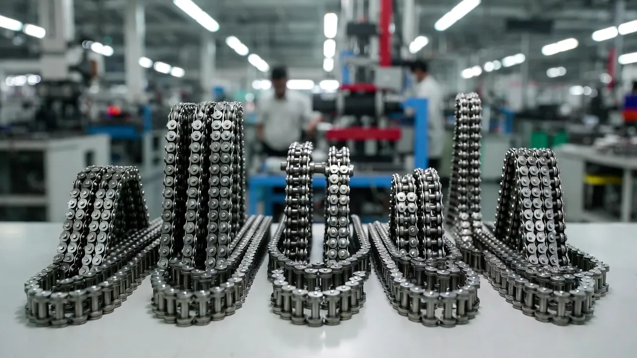
Where Heavy Duty Equipment Demands a Simplex Chain Drive
Heavy machinery is rarely a uniform environment. Conveyor frames, press drives, and lifting mechanisms each impose distinct load profiles, speed ranges, and misalignment tolerances. Understanding which specific drive point calls for a simplex configuration — and why — prevents premature failure and costly downtime.
Primary Drive Transmissions in Industrial Presses and Reducers
The main input shaft of a hydraulic baler, stamping press, or shaft-mounted reducer typically operates at moderate speed (50–200 RPM) but transfers very high torque to downstream components. A large-pitch simplex chain such as the 16B-1 or ANSI 80 suits this position because single-strand construction concentrates the entire load on one set of plates and rollers, making it easier to verify wear progression through elongation measurement. The symmetric loading also means the chain seats consistently into sprocket valleys, reducing the polygon effect that causes vibration at higher speeds.
Secondary Conveyor Drive Shafts in Material Handling Systems
Once power leaves the primary reducer, it distributes across multiple conveyor axes via cross-shaft drives. These secondary positions often run at 60–150 RPM with moderate torque — exactly the operational window where a 12B-1 or ANSI 50 simplex chain performs at peak efficiency. At this speed range, lubrication retention in the bush-roller interface is adequate for bath or drip-feed systems, and the simpler single-strand construction reduces alignment sensitivity compared with multi-strand configurations.
Takeup and Tensioning Mechanisms on Heavy Belt Conveyors
Gravity or screw-type takeup assemblies use short-pitch simplex chains to drive the tensioning carriage or adjust the counterweight system. Here, the chain sees intermittent, low-speed movement combined with sudden tension spikes when the belt load shifts. A stainless-steel or nickel-plated simplex chain in the 08B-1 range handles corrosion from wash-down cycles while absorbing shock loads through the compliance of properly lubricated roller-bush contacts.
Material Engineering Behind Long-Service Simplex Chains
The structural integrity of a simplex roller chain under heavy loads depends entirely on how each component is processed — not just what alloy is selected. The industry has refined these treatments over decades, and understanding them helps procurement teams make more effective supplier comparisons.
Case-Hardened Pins
Pins undergo carburising to achieve surface hardness of HRC 58–62 with a tough core at HRC 32–38. This gradient resists rotational fatigue at the pin-bush contact. Through-hardened pins crack under shock loads; case-hardened geometry flexes without catastrophic fracture.
Shot-Peened Side Plates
Controlled shot-peening introduces compressive residual stress into the plate surface layer. Fatigue cracks typically initiate at the waist radius under cyclic tensile loading — shot-peening counteracts this, extending plate fatigue life by 30–50% under heavy duty cycles.
Sintered Bush Technology
Powder-metallurgy bushings contain interconnected pore networks that store lubricant internally. Under load, contact pressure forces oil to the wear surface; when pressure drops, capillary action draws it back in — reducing lubrication frequency on hard-to-access drives significantly.
Precision-Ground Rollers
Ground-finish rollers maintain dimensional tolerance within ±0.01 mm, ensuring uniform contact across the sprocket tooth profile. Loose tolerance causes rollers to enter tooth valleys at varying impact angles, accelerating both roller and sprocket wear under cyclic impact loads.
Lubrication Strategies That Protect Simplex Chains Under Continuous Load
Even the highest-grade simplex chain will fail prematurely if lubrication is inadequate or misapplied. Heavy-duty applications involving shock loads or elevated temperatures demand a systematic approach rather than periodic manual oiling.
Load Calculation and Chain Selection for Heavy Applications
Sizing a simplex chain incorrectly is one of the most common and costly mistakes in drive system design. The process involves several interdependent variables that must be resolved in sequence to arrive at a reliable selection.
Step One — Determine Design Power
Design power is not simply the rated motor output. It is the transmitted power multiplied by a service factor that accounts for load type, daily operating hours, and drive geometry. Shock loads from crushers, rock breakers, or reciprocating compressors carry service factors of 1.5–2.0 when operating more than 16 hours per day. Failing to apply this factor is the primary reason chains selected on nominal power alone fail within months rather than years.
Step Two — Determine Sprocket Speed and Pitch Diameter
The small sprocket (driver) speed and desired velocity ratio fix the large sprocket tooth count. Engineering practice specifies a minimum of 17 teeth on the driver sprocket to reduce the polygon effect and tooth impact velocity. As pitch increases, the allowable speed drops — a 25.4 mm pitch simplex chain should not exceed approximately 600 RPM on the small sprocket without a detailed vibration analysis.
Step Three — Select Chain Pitch and Verify Fatigue Life
Once design power and sprocket speed are fixed, the chain pitch is selected from the manufacturer’s power rating tables at the small sprocket RPM. A secondary verification checks that the working tension — calculated as design power divided by chain velocity — remains below the allowable load listed in the specification table. This dual check catches edge cases where a chain passes the power-rating table but operates near its fatigue limit under continuous heavy loading.
Corrosion Resistance Options for Harsh Australian Environments
Australia’s industrial landscape spans tropical humidity in Queensland, coastal salt exposure in Perth and Darwin, and the abrasive red-dust environments of Western Australian mining sites. Standard carbon-steel simplex chains are not adequate for these conditions without supplementary protection.
Zinc-Nickel Plating
Electrodeposited zinc-nickel alloy (12–15% nickel) provides barrier corrosion protection equivalent to hot-dip galvanising at a fraction of the dimensional impact. Chain components maintain original tolerances — the preferred factory option for coastal-zone drives where salt-laden air causes rapid rust on bare steel.
Stainless Steel Construction
Grade 304 simplex chains suit food-processing, brewing, and pharmaceutical lines where wash-down with caustic or acidic cleaning agents is routine. Grade 316 handles chloride-rich environments such as seafood processing plants. The trade-off is approximately 15–20% lower tensile strength versus alloy-steel chains.
Nickel-Plated Chains
Bright nickel plating offers aesthetic appeal alongside moderate corrosion resistance, making it a common choice for visible drives in packaging machinery. Nickel does not sacrifice tensile strength to the same degree as stainless, but is not recommended for pH-extreme or high-chloride wash environments.
Self-Lubricating / PTFE-Coated
PTFE-impregnated sintered bushings reduce dependency on external lubrication in dusty or contaminated environments. Mining conveyor tails, aggregate screening plants, and cement processing lines benefit from this technology’s combination of low friction and resistance to particle ingestion.

Installation Best Practices to Maximise Service Life
A high-grade simplex chain installed incorrectly will fail faster than a mid-grade chain installed with care. The following practices address the most common installation errors observed in Australian heavy-industry maintenance environments.
- ✔Shaft parallelism: Verify shaft centres are parallel within 0.5 mm per metre of shaft spacing using a precision spirit level or laser alignment tool. Angular misalignment generates lateral plate wear and accelerated sprocket flange erosion.
- ✔Sprocket alignment: Both sprockets must sit in the same plane. Use a straight edge across the sprocket faces or a laser alignment system. Even 1° of lateral offset produces measurable wear within 500 operating hours.
- ✔Correct chain sag: Horizontal drives require 2–3% of centre distance as sag on the slack strand. Over-tensioning increases bearing loads by 30–40% and accelerates pin and bush wear.
- ✔Master link orientation: Install spring-clip connecting links with the closed end of the clip facing the direction of travel. On heavy-duty chains above 16B-1, use interference-fit press-fit links for full plate fatigue strength.
- ✔Pre-lubricate before first start: Even factory-lubricated chains benefit from a second application of the specified oil at every bush-pin interface before initial commissioning.
- ✔Run-in cycle: Operate at 50% of rated load for the first 2–4 hours. This seats the rollers into their sprocket valleys and allows the lubrication film to distribute fully before full-load stresses are applied.
Monitoring Chain Wear and Establishing Replacement Intervals
Predictive maintenance on simplex chain drives relies on two primary measurements: chain elongation due to wear and sprocket tooth profile assessment. Replacing chain at the right interval — not too early, not too late — is central to minimising lifecycle cost on heavy machinery.
A simplex roller chain elongates as the pin and bush bore wear progressively. The generally accepted replacement threshold is 2% elongation over a 30-link reference length. Beyond this point, the chain rides higher on the sprocket tooth flanks rather than seating in the root, causing accelerated tooth wear and increasing the risk of tooth jump under load. For a 25.4 mm pitch chain, a 30-link reference spans 762 mm new; replacement is indicated when that span measures 777 mm or more.
Sprocket teeth should be inspected simultaneously. Wear produces a characteristic hook shape on the drive-side tooth face — once this profile is visible, installing a new chain on worn sprockets resets the elongation clock to near-zero because the new chain pitches differently from the worn tooth form. Best practice replaces both chain and sprockets together. Discover the full range of industrial drive components at Gear Drive, where heavy-duty simplex chain solutions are matched to your specific machinery requirements.
Comparing Simplex Chain Grades: Standard, Heavy Series, and Extended Pitch
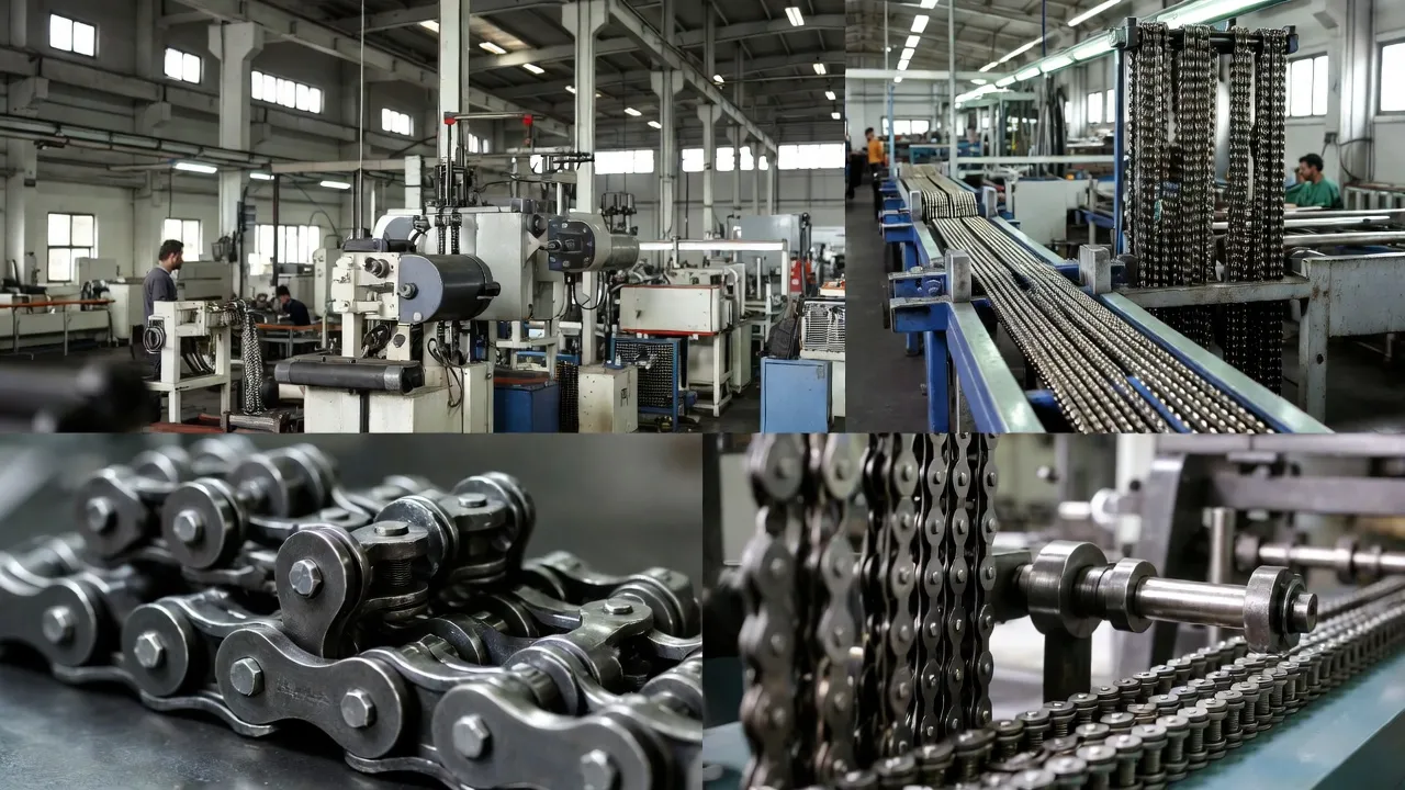
Heavy series simplex chains are identifiable by the suffix “H” after the chain designation (e.g., 12B-1H). The increased plate thickness does not alter the pitch or roller diameter, meaning heavy-series chains are fully interchangeable with standard sprockets — a significant advantage when upgrading an existing drive without modifying the drive geometry.
Our engineering team at Gear Drive Australia provides load calculation support, application-specific chain selection, and custom-length assembly services for heavy-duty installations across mining, manufacturing, and materials-handling sectors.
Frequently Asked Questions